Most of the lockout failures we've identified through customer feedback and on-site inspections are not caused by procedural gaps. Rather, they stem from the fact that the equipment used is physically incapable of keeping the energy isolation device in the off position. For example, a padlock attached to a valve handle that can still be rotated a quarter turn, or a padlock on a circuit breaker that becomes ineffective because the circuit breaker automatically resets. Warning labels on plugs can be easily torn off by anyone passing by. While these three scenarios may appear to comply with regulations during on-site inspections, they will completely fail the day someone enters the equipment to perform work.
Selecting a lockout device is first and foremost a mechanical decision, and only secondarily a managerial one. You need to match the equipment to the energy source, and the OSHA 1910.147 standard provides the definitions necessary to do this correctly.
Start with the energy inventory, not the catalog
1910.147(b) defines an energy source as electrical, mechanical, hydraulic, pneumatic, chemical, thermal, or other. List every source on the machine, find the device that isolates it, check whether that device can be locked, then pick hardware. Plants routinely miss thermal, pneumatic and stored mechanical energy because none of them are visible during a normal shift: hot product in a jacket, an unpowered conveyor on an incline, a spring-loaded clamp still cocked with the air off.
One line in the standard settles a lot of arguments. 1910.147(b) states that push buttons, selector switches and other control circuit type devices are not energy isolating devices. An emergency stop cannot serve as isolation, because it does not physically break the energy path. Where a control circuit is all you have, the standard's answer is a full employee protection demonstration under 1910.147(c)(3), a far harder document to defend than a correctly specified device. Note also that 1910.147(c)(2)(iii) requires equipment installed or substantially modified after January 2, 1990 to be designed to accept a lockout device.
Electrical isolation: breakers, disconnects, and cords
Molded-case breakers are easy to isolate and hard to lock, because the handle sits flush with the panel. The device either clamps the handle to the panel or covers it and locks through the panel openings, and it has to hold all poles of a multipole breaker together. Handle sizes vary enough that one circuit breaker lockout device will not cover every panel in a building, so check the frame before ordering a plant-wide set.
Disconnects and rotary switches usually accept a padlock directly, which makes them the simplest isolation point on a machine. Check that the device blocks the handle in the off position without preventing the door from opening, and without letting the handle be operated while the door is open.
Cord-and-plug equipment sits outside the standard only when the plug stays under the exclusive control of the employee doing the work, per 1910.147(a)(2)(iii)(A). On a floor where three shifts share one outlet, that condition is usually false, and a plug lockout enclosing the plug and receptacle is the cheaper answer. Whichever point you lock, 1910.147(d)(6) requires verification: operate the normal start control, watch for movement, then return it to off.
Valve and fluid isolation: match the mechanism, not the pipe size
Pipe diameter is irrelevant to device selection; the lever or handwheel geometry decides it. Two valves of the same bore in one plant often need two different devices. Lever-operated ball, butterfly and plug valves need a device that captures the lever against the body. Rising-stem gate valves need one that blocks both handwheel rotation and stem travel. Universal devices suit mixed inventories, but a universal that fits everything fits something loosely, so reserve it for valves you lock a few times a year and use a fitted valve lockout device on anything locked weekly.
When a valve seat leaks, no amount of handle locking makes the line safe. 1910.147(b) lists blank flanges and bolted slip blinds inside its own definition of a lockout device, which puts positive isolation in the selection logic rather than at the end of it. Once the valve is locked, bleed or vent the isolated section and keep the vent open. A locked valve with a pressurized section behind it has solved half the problem.
Fluid power and stored energy
Compressed air and hydraulic oil are the sources plants forget, because the machine is quiet once the air is off. Locking the air disconnect is step one; step two is the coupling, which anyone can reconnect in seconds. A pneumatic lockout device that covers the male plug or female coupling prevents reconnection and keeps the line visibly open to atmosphere. Receivers still hold energy after the disconnect closes, so leave the drain open while work is in progress.
Hydraulics store energy in accumulators, raised rams and hose elasticity. Lock the isolation valve, bleed the accumulator, block anything held up by pressure, then verify with a gauge or by attempting a cycle. Check that the gauge sits on the isolated side of the valve; otherwise it reads zero while the locked section stays pressurized.
1910.147(d)(5) goes further than locking: stored or residual energy must be relieved, disconnected, restrained or otherwise rendered safe, with verification continuing where energy can reaccumulate to a hazardous level. Springs, raised loads, flywheels and inclined conveyors move with all power locked out, and 1910.147(c)(5)(i) names wedges, key blocks, adapter pins and self-locking fasteners as hardware the employer provides. Blocking has to work in both directions of travel, because a screw conveyor can be turned from either end.
Group lockout and multi-point isolation
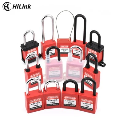
One worker, one lock, one isolating device is the simple case. A crew of four, six isolation points and a shift change in the middle is the normal one, and 1910.147(f)(3) requires the crew to get protection equivalent to a personal lock. A lockout hasp lets each worker fit a personal padlock to one isolating device, so nobody restores energy while someone is still inside the machine. Fit a hasp long enough for the crew's locks plus the operations lock, and no longer than that.
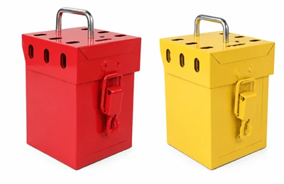
On multi-craft jobs, 1910.147(f)(3)(ii)(D) requires each authorized employee to fit a personal lockout device to the group lockout device or group lock box when work begins and remove it when work stops. A group lock box is what makes the shift-change transfer orderly and gives the coordinator a physical way to see whether everyone is out: machine keys inside, one padlock per person on the box.
The four hardware tests in 1910.147(c)(5)(ii)
Auditors rarely ask which brand you bought. They ask whether the hardware meets four criteria, and whether the plant applies them consistently.
Durable (c)(5)(ii)(A): the device must withstand its environment for as long as it is exposed to it. That rules out plastic bodies near hot work and unsealed locks in washdown areas.
Standardized (c)(5)(ii)(B): standardized within the facility in at least one of color, shape or size. Pick one and document it, because mixed colors bought by different departments undermine the idea.
Substantial (c)(5)(ii)(C)(1): resistant to removal without excessive force or unusual techniques such as bolt cutters. If a screwdriver frees it, it is a tag with extra steps.
Identifiable (c)(5)(ii)(D): the device indicates who applied it. Engraved safety padlocks and photo ID tags both work; a shared pool of unmarked locks does not.
The same paragraph adds that lockout and tagout devices must be the only devices used for controlling energy, and must not be used for other purposes. A padlock left on a toolbox, a gate or a gang box is the fastest way to make the lock's meaning ambiguous, and it is the habit an inspector notices first.
Selection matrix: energy source, device, verification
Use this as a starting point for the energy control procedure, then confirm fit on the actual machine. Verification steps follow 1910.147(d)(6), which requires the authorized employee to confirm isolation and de-energization before work begins.
|
Energy source |
Typical isolating device |
Lockout hardware |
Verification step |
|---|---|---|---|
|
Electrical, panel |
Molded-case circuit breaker |
Handle clamp or panel-opening device, all poles held |
Attempt normal start; confirm no movement |
|
Electrical, feeder |
Disconnect or rotary switch |
Handle hasp padlock or handle-blocking device |
Attempt start at local control; check with tester |
|
Electrical, portable |
Cord and plug under exclusive control |
Plug enclosure lockout on plug and receptacle |
Confirm plug is locked and under the worker's control |
|
Valve, lever |
Ball, butterfly, plug valve |
Fitted lever-locking device, hasp for crews |
Cycle the valve; confirm the lever cannot move |
|
Valve, handwheel |
Gate or globe valve |
Handwheel and stem lockout device |
Open downstream drain; confirm no flow |
|
Pneumatic |
Air disconnect and coupling |
Disconnect lockout plus quick-coupler lockout |
Confirm line open to atmosphere; drain receiver |
|
Hydraulic |
Isolation valve and accumulator |
Valve lockout plus blocking for raised loads |
Bleed accumulator, read gauge on isolated side |
|
Stored mechanical |
Raised load, spring, flywheel |
Wedges, key blocks, adapter pins or blocks |
Test movement in both directions |
|
Capacitive or thermal |
Drive, capacitor bank, hot line |
Locked discharge switch, isolation plus cooldown |
Meter and temperature readings before opening |
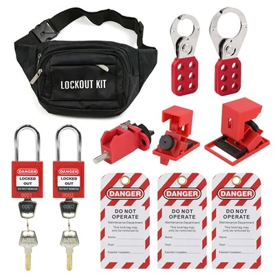
HiLink builds lockout tagout hardware for plants that have to defend their choices to an auditor. If you are specifying hardware for a machine you have never locked out before, our lockout tagout kits cover the common combinations of padlocks, hasps, valve devices and tags in one case, which is usually the fastest way to bring a mixed plant to a consistent standard. Send us your energy list and we will tell you which device families fit it.
Questions EHS teams ask before specifying hardware
Do we need lockout, or is tagout enough? 1910.147(c)(2)(ii) requires lockout whenever the isolating device is capable of being locked, unless you can demonstrate that a tagout system provides full employee protection under 1910.147(c)(3). Tags do not physically restrain the device, as 1910.147(c)(7)(ii)(A) acknowledges. Tagout belongs on isolating devices that were never designed to take a lock, not on convenient ones.
How long can a lockout device stay fitted? There is no time limit in the standard, but durability is defined by exposure. A device left on outdoor equipment for months has to survive weather, UV and temperature swings, so choose stainless steel or reinforced nylon bodies where a lock is fitted for the long term rather than for a single shift.
Who checks that device selection is still correct? 1910.147(c)(6) requires a periodic inspection at least annually, performed by an authorized employee other than the one using the procedure being inspected. Build the hardware check into that visit: confirm each device still fits the isolating device it was bought for, and that nothing has been swapped or repurposed since the last inspection.